Getting started with LEDs
Introduction to LED strips
Rotorflight supports up to 32 individually addressable WS2811/2812 RGB LEDs. You can control them with just one data pin, and set the brightness and color of each LED individually. LEDs can have different functions, for example display a color, visualize warnings or battery state, or just blink. This walk-through will show you how to set up a simple LED strip with some scale lights.
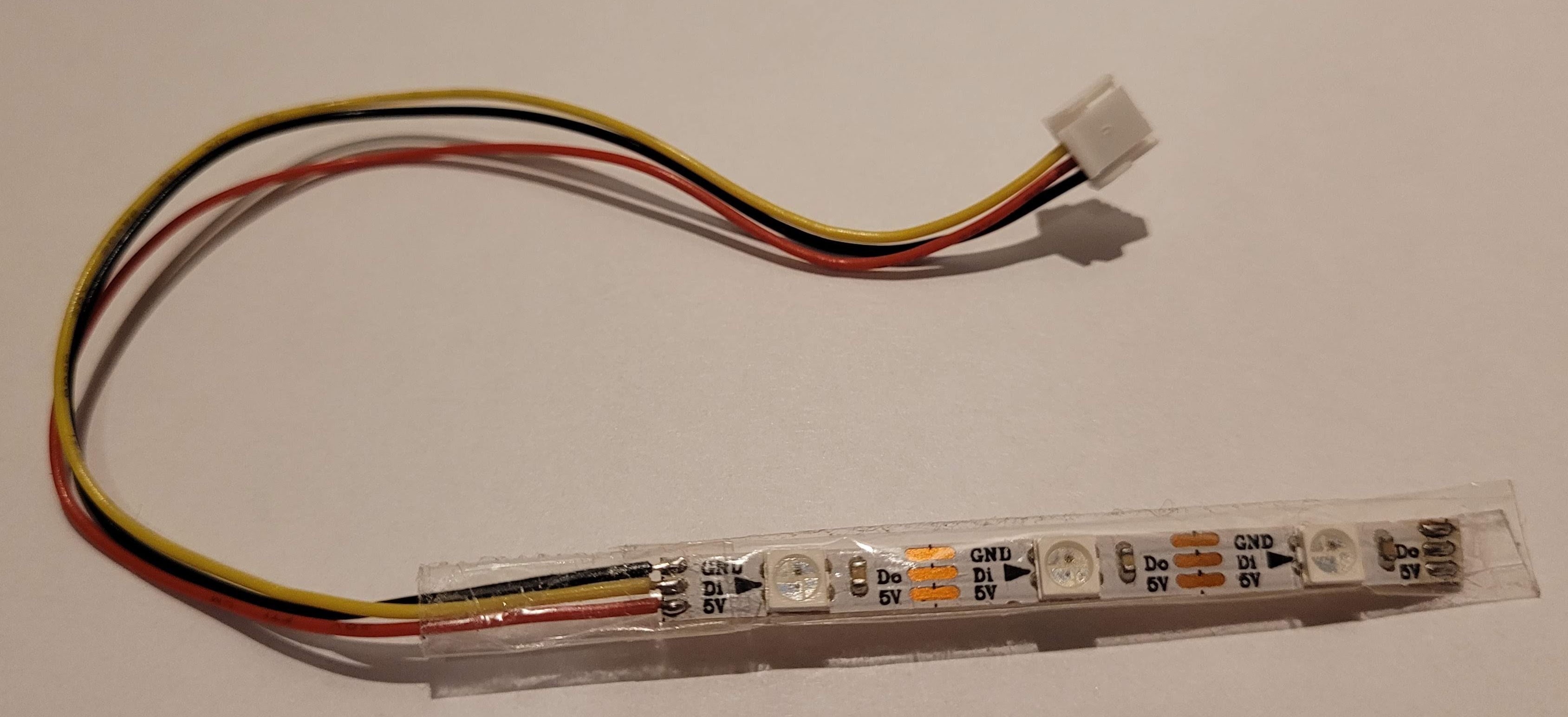
Each LED has 4 pins: 5V, ground, data in and data out. The FC should be connected to data in of the first LED. Data out of the first LED should be connected to data in of the second LED. And the data out of the second LED should again be connected to data in of the third LED. And so on.
There are ready made WS2812 strips with 30, 60 or 144 LEDs per meter. That's great for testing or maybe on the boom for some night flying, but there are also more conventional WS2811 5mm and 8mm LEDs available. Those are more suited for scale lighting.
There are quite a lot of tutorials/videos for Betaflight, and Rotorflight supports all the functions of Betaflight 4.3. In addition, Rotorflight supports scale lights, with which you can program anti-collision lights, strobe lights or landing lights. Here we'll focus on those scale lights.
Create a LED_STRIP resource
In order to use a LED strip, you'll need a LED_STRIP resource to which you can connect your LEDs. A LED_STRIP resource requires a timer and DMA should be enabled.
Some FCs might already have a LED_STRIP resource and then you can just use that pin. But if you want to use another pin on your FC, or if your FC doesn't have a LED_STRIP resource, you'll need to do some resource remapping. For this walk-through I'm going to use the Radiomaster Nexus, so go to the CLI and remap TX6 to LED_STRIP.
Now go to the Configuration tab and enable LED_STRIP under Features. Press Save and reboot.
Testing hardware
A piece of LED strip is ideal for testing. I'll be using one with 3 LEDs connected to Port B on the Nexus. Wiring is simple: just connect 5V, ground and LED_STRIP (formerly known as TX6) to the strip.
The LED Strip tab
Now go to the LED Strip tab. Note that this tab will only be visible if you have the LED_STRIP feature enabled under Configuration.
We're going to define:
- a green navigation light that also functions as a strobe
- a red ACL light that slowly blinks
- a white landing light that can be operated from the TX.
Connect the Nexus to the Configurator using USB. 5V will now be available on port A, B and C. If you're using many LEDs, consider using an external 5V power supply.
Define the 3 LEDs
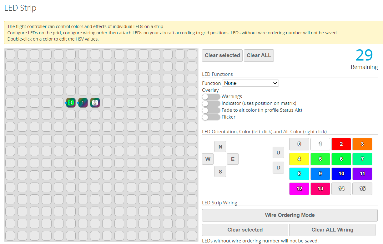
- Click on Wire Ordering Mode. The 16x16 matrix will become greenish.
- Select a square in the matrix. A '0' should now be displayed in it.
- Select Color as Function
- Now select another square in the matrix. A '1' should now be displayed in it.
- Select Color again as Function
- Select yet another square in the matrix. A '2' should now be displayed in it.
- Select Color as Function
- Press Save
Your screen might now look like this, although the actual position of the three squares will likely be different:
Create the green navigation light
- Select the square with '0' in it
- In the color palette, left-click on green. The LED should now light up.
- If you find the LED too bright, adjust the overall LED brightness under LED Strip Global Settings
- Enable Blink and set one checkmark. The LED wil now shortly turn off (=black).
- In the color palette, right-click on white. Now the LED will shortly flash a white light.
- Press Save
Create the red anti-collision light
- Select the square with '1' in it
- Select Blink and set some check marks next to each other
- Right-click the red color. The second LED should now flash red
- Press Save
Create the white landing light
- Select the square with '2' in it
- Enable the Fade to alt color feature
- Left-click white. The LED should now light up
- Select Status Alt next to Profile, under LED Strip Global Settings. The LED should now dim.
- Set Fade rate to 10 to dim slowly
- Press Save
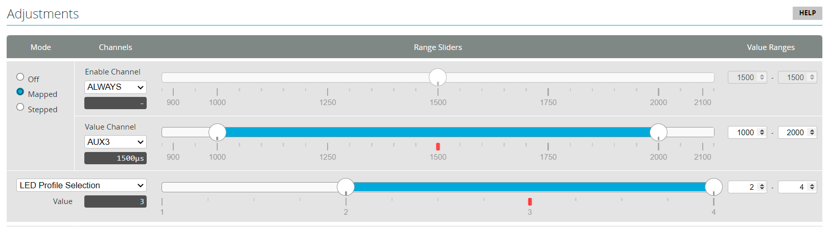
- You can use Adjustments to switch the LED profile from your transmitter. It might look something like:
Here's another video showing the techniques used in this Quick Start on a Walkera 4F200LM, for which I used two 3mm and four 5mm LEDs.
Molex PicoBlade bus
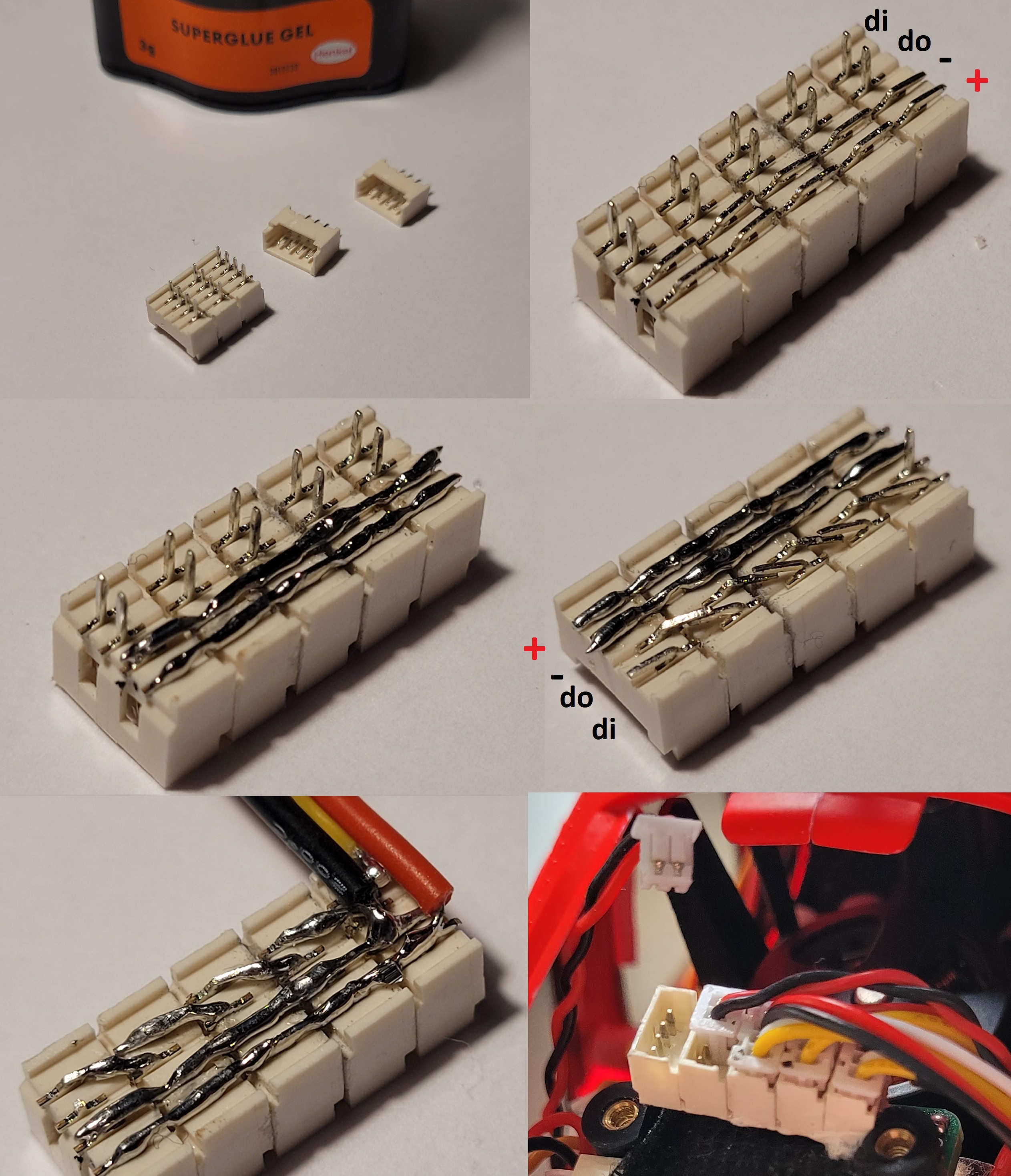
Here's a simple bus system for connecting individual LEDs using 4-pin Molex PicoBlade connectors. It can be used for connecting individual WS2811/2812 LEDs as well as conventional LEDs.
Conventional LEDs should come after the WS2811/2812 LEDs since they don't support data in and data out. Also, you can use 2-pin PicoBlade connectors for them.
Building the PicoBlade bus
- Glue some 4-pin PicoBlade headers together
- Bend the pins for 5V and GND so they form two rails
- Carefully solder the 5V and GND rails
- Bend the data out pin of the first header to the data in pin of the second header and repeat
- Solder the data out pins to the next data in pins
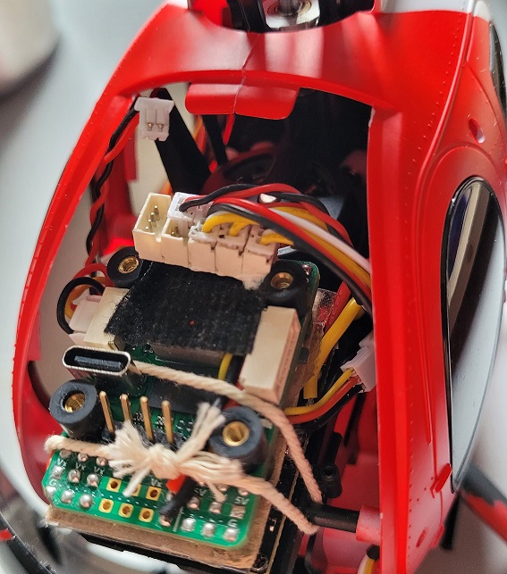
- Connect wires for 5V, GND and data in to the bus
- Isolate the bottom of the bus with hot glue or epoxy
- Connect the bus to the FC
Remapping to LED_STRIP
Radiomaster Nexus
On the Nexus Port B is the best choice for creating a LED_STRIP resource. Port B provides RX6 and TX6 by default. To remap TX6 to LED_STRIP, enter the following in the CLI:
resource SERIAL_TX 6 NONE
resource LED_STRIP 1 C07
timer C07 AF3    # TIM8, default is also AF3
dma pin C07 0    # default is NONE
save
Note that although we remapped TX6, RX6 is still there and functional.
Alternatively you can remap RX6 to LED_STRIP:
resource SERIAL_RX 6 NONE
resource LED_STRIP 1 C06
timer C06 AF3    # TIM8, default is also AF3
dma pin C06 0    # default is NONE
save
FlyDragon F722
The FlyDragon F722 has a built in LED 'strip' with just one LED. It has the Warning overlay enabled by default and is connected to the FC using pin B08. However, the data out pin of that LED isn't exposed, so you have to remap some other port to LED_STRIP to make use of your own LEDs. There are several options: SCL, SDA, RPM-S and F.Port. SCL and SDA are located on the GPS port, which also provides 5V. Using SCL or SDA is preferred because they can have their own dedicated timer.
1. Remap SCL to LED_STRIP
To remap SCL to LED_STRIP, enter the following in the CLI:
resource I2C_SCL 1 NONE
resource LED_STRIP 1 B06   # default is B08
timer B06 AF2              # TIM4
dma pin B06 0
save
2. Remap SDA to LED_STRIP
To remap SDA to LED_STRIP, enter the following in the CLI:
resource I2C_SDA 1 NONE
resource LED_STRIP 1 B07   # default is B08
timer B07 AF2              # TIM4
dma pin B07 0
save
3. Remap RPM-S to LED_STRIP
RPM-S isn't connected to VBec and supplies 5V, which is all right for a couple of LEDs.
To remap RPM-S to LED_STRIP on the FlyDragon V2 or V2.2, enter the following in the CLI:
resource LED_STRIP 1 A15   # default is B08
timer A15 AF1              # TIM1
dma pin A15 0
save
To remap RPM-S to LED_STRIP on the FlyDragon V1, enter the following in the CLI:
resource LED_STRIP 1 A08   # default is B08
timer A08 AF1              # TIM1
dma pin A08 0
save
4. Remap F.Port to LED_STRIP
Be careful: F.Port uses VBec, which might be too high for your LEDs. Most LEDs require 5V.
resource LED_STRIP 1 A02   # default is B08
timer A02 AF1              # TIM2
dma pin A02 0
# Change motor 1 timer from TIM2 to TIM5
timer A00 AF2
save
Flywing HELI405
You can remap SBUS to LED_STRIP on the Flywing HELI405. To do this, enter the following in the CLI:
resource SERIAL_RX 2 NONE
resource LED_STRIP 1 A03
timer A03 AF2
dma pin A03 1
save