Remapping
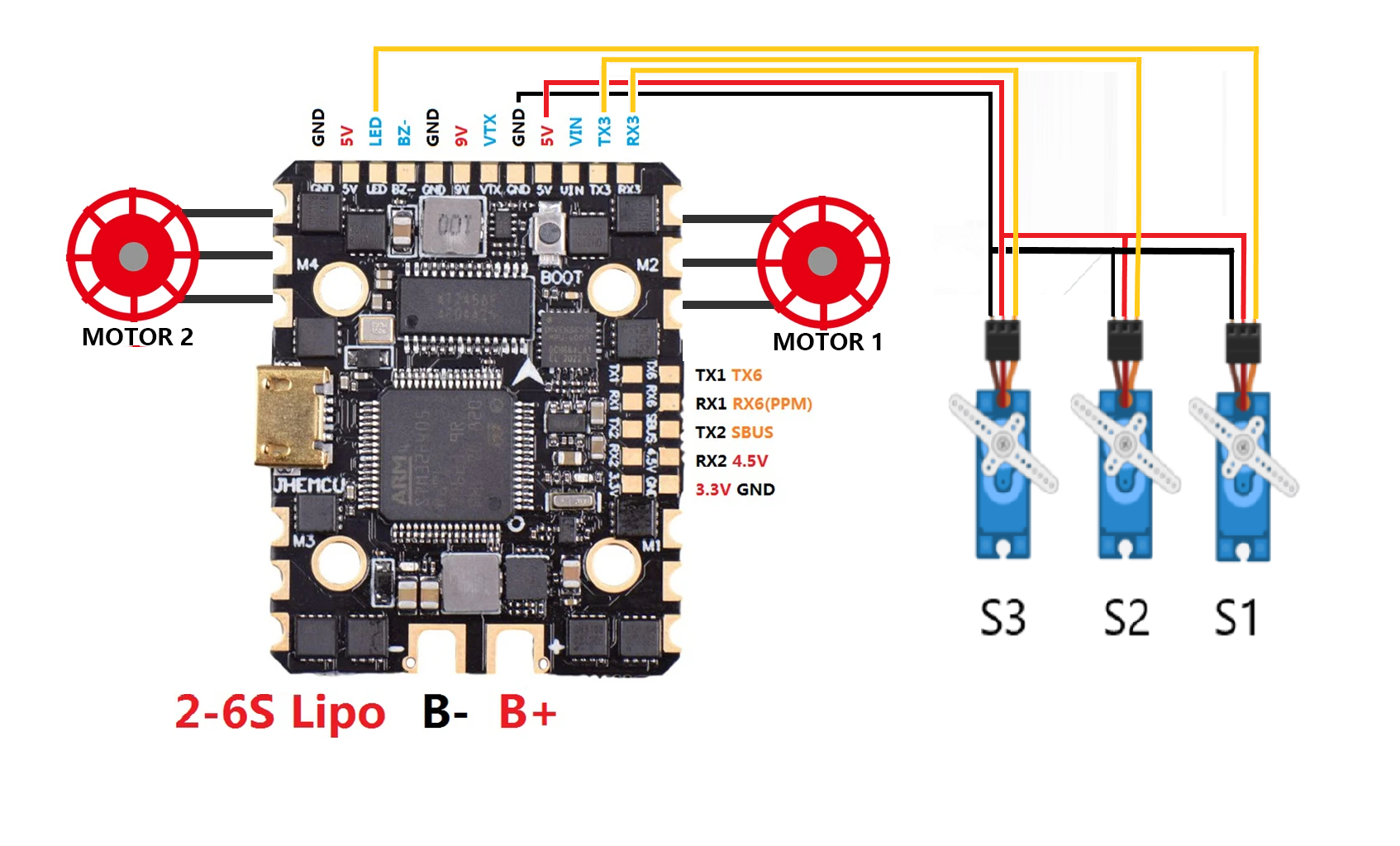
Rotorflight is based on Betaflight which is generally used to control drones. Unfortunately, drones do not have servos and have more motors than we need for a helicopter. In order to use servos we must remap our boards so that we have a pad to connect the servos to.
If using a commercial Rotorflight controllers (NEXUS, Flydragon, Flywing, MatekG474 etc). This step is not required as these controllers are supplied with servos already configured
Disclaimer
The pin labeling on commercial flight controllers refers to what the manufacturer has assigned as a function to that pin, in reality these pins are connected to the mcu, and with the power of RF, we can reassign these pins to other functions depending on the available resources on that pin, (you can consult the mcu data sheet STM32 alternate function mapping table to view all the available resources on a particular pin).
Key concepts
Before you start remapping your drone FC to be used with Rotorflight, keep in mind the following.
1- Although it is not necessary, but it is advised to keep your cyclic servos on the same Timer.
2- If you wish to use a narrow band tail servo, then assign that servo to separate timer.
3- Main motor esc output should on a separate timer.
4- In case you are using a PWM controlled esc then Rotorflight will require an rpm signal for governor and RPM Filtering, RPM input should be on a 32bit separate timer (TIM2 or TIM5).
Custom defaults remapping spreadsheet
Spreadsheet for remapping Betaflight targets for use with Rotorflight. The spreadsheet re-allocates features for motors and servos and configures associated timers and dma.
- Please 'make a copy'.
Rotorflight remapping spreadsheet v1.4.1
Rotorflight remapping spreadsheet v2.0
Rotorflight Hardware config and remapping video
Importing new targets
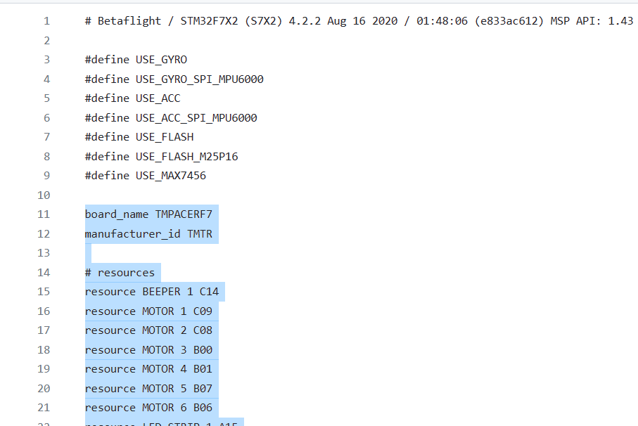
Some targets in the betaflight target repository have additional #define lines above board_name. Please do not chose them. In the example below copy only from board_name down. The Board_name MUST be the first line in the spreadsheet.
Configuring a Motor output
Configuring a Frequency input
The frequency input pin must be connected to a timer with exclusive access. In other words, there must be a free timer, not used by anything else, and one of its positive channels must be available on a pin that is connected to the FC's solder pads. Negative channels, like CH3N, can't be used as inputs. Once we know which timer and pin we can use, it can be configured for frequency sensor use.
We recommend that Freq inputs are allocated to pins that have Timer 2 or Timer 5 available. If 2 Freq inputs are required (e.g. Motorized tail) then both inputs can share the same timer. In the remapping spreadsheet these pins are indicated by the green box marked Freq.
In this example, we have chosen to use the LED_STRIP pin as our frequency input. We see there is only one option (Timer1) on AF1. We can use this pin but must not allocate any of the Servos or Motors to Timer1. Only the motor pins share this timer so we can choose either AF2 (timer3) or AF3 (timer8).
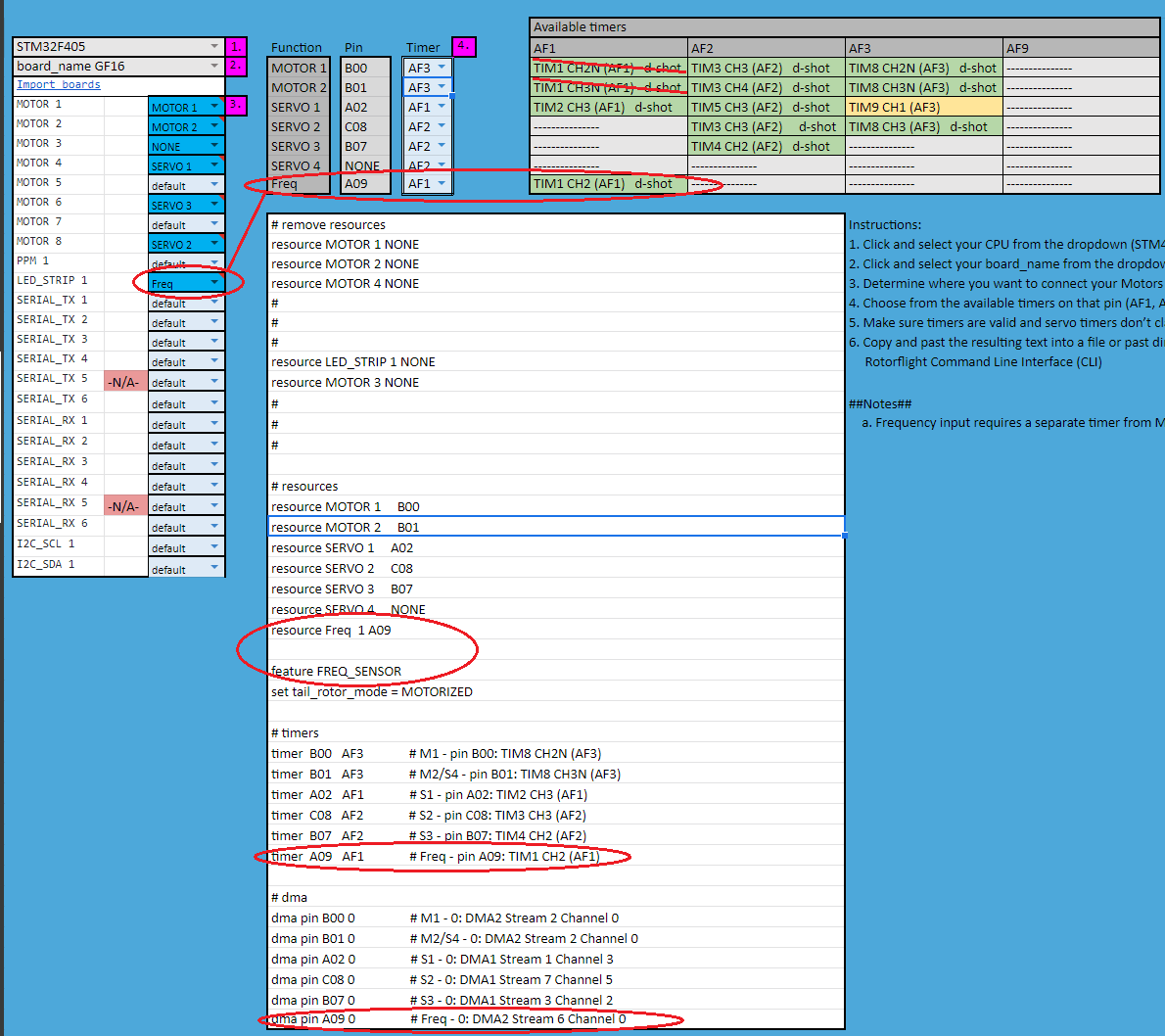
The lines which configure the frequency signal
resource LED_STRIP 1 NONE
resource Freq  1 A09
timer A09 AF1 # Freq - pin A09: TIM1 CH2 (AF1)
dma pin A09 0 # Freq - 0: DMA2 Stream 6 Channel 0