DIY board - Betaflight FC
Rotorflight is a fork of the popular Betaflight project commonly used for drones. This means that all of the drone boards designed for betaflight are also compatible with Rotorflight. Drones most commonly use 4 motors and do not have servos so we need to do some additional configuration to add these items (as shown below).
Flashing Rotorflight
Remap Betaflight board
Example: M1 with DarwinFPV 15A
The OMPHOBBY M1 is a small double brushless helicopter with an all-up weight of about 120g. The stock FC is so-so and has some peculiarities, such as a huge deadband around center and a tail that sometimes spins volatile.
It's fairly easy to replace the stock FC and ESC with an AIO whoop board. Here we're using the DarwinFPV 15A.
- It's able to do 15A continuously with peaks of 17A, which should be enough for the main motor.
- It also has a 2A 5V BEC, which is plenty for the servos.
- There are enough connections (pads) for the servos, ELRS and -optional- an OpenLager blackbox logging device.
The receiver used here is a BETAFPV ELRS Lite.
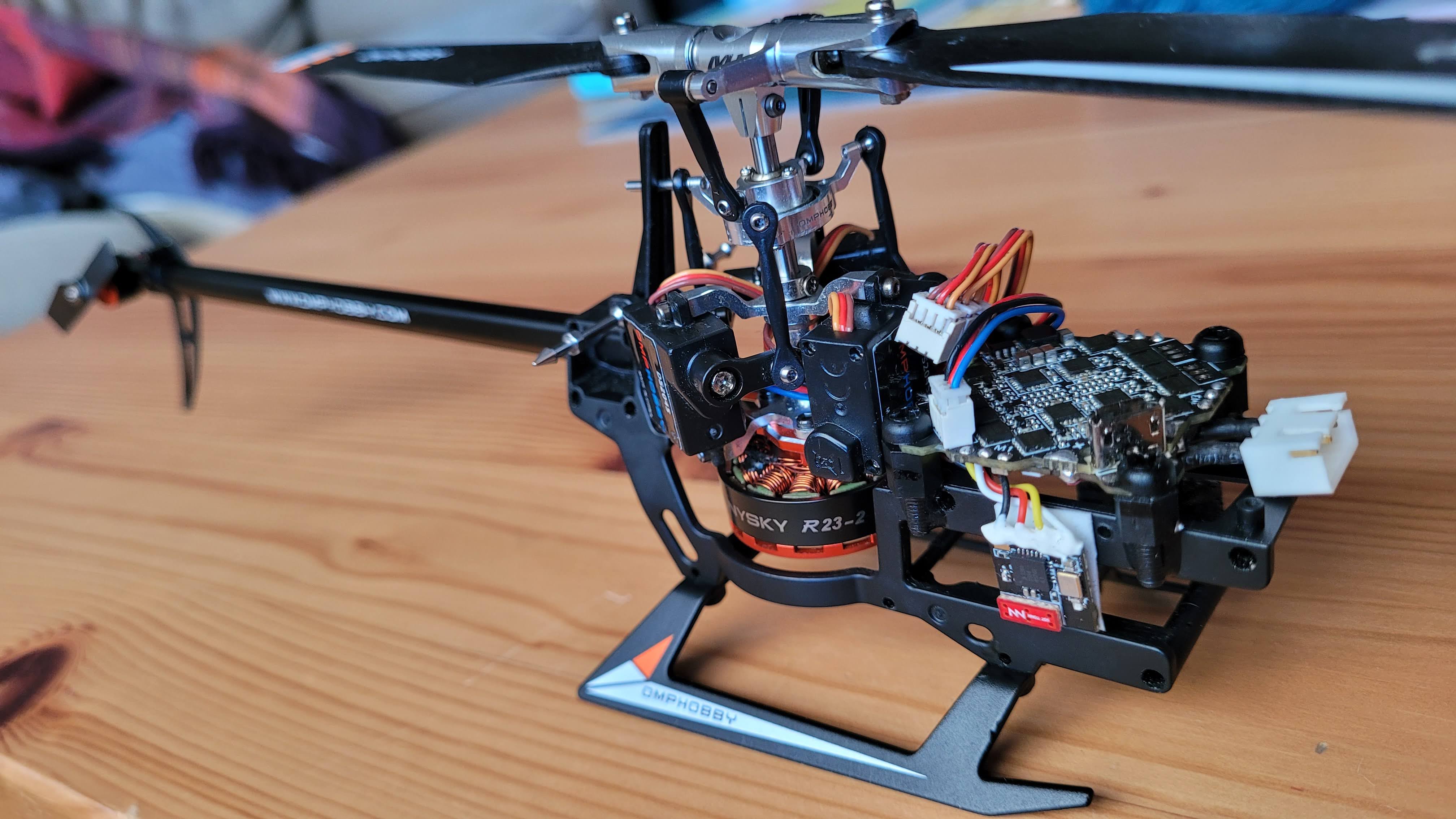
There's also a DarwinFPV 15A with built-in ELRS receiver, but we can't use that version since it uses SPI - which isn't supported by Rotorflight.
Build notes
- The AIO is mounted to the M1 frame with some plastic M3 spacers and screws. The spacers are glued to the M1 frame with some epoxy, after cutting the thread underneath them slightly to make a perfect fit.
- The servo connectors are three Molex PicoBlade connectors glued together (similar to this bus), then connected to the FC using 5 wires (5V/GND using 28AWG, S1/S2/S3 with 30AWG). The underside of the bus is reinforced and insulated with epoxy.
- None of the servo or tail motor wires are modified, and only the copper connectors on the main motor wires were removed.
- All wires soldered to the PCBs are secured with some electronics-friendly silicon glue, which will reduce the risk of solder joints breaking or wires loosening during flight.
- The ESCs were flashed with Bluejay version 0.21, so we can use bi-directional Dshot with RPM telemetry for filtering and governing.
- The pre-soldered capacitor on the DarwinFPV 15A has been removed.
Here's a view from the left. Note that the board is hard mounted, which is possible if the gyro on the DarwinFPV 15A can cope with strong vibrations or if the heli is extremely well balanced. This board has an MPU-6000 gyro and the heli is pretty well balanced.
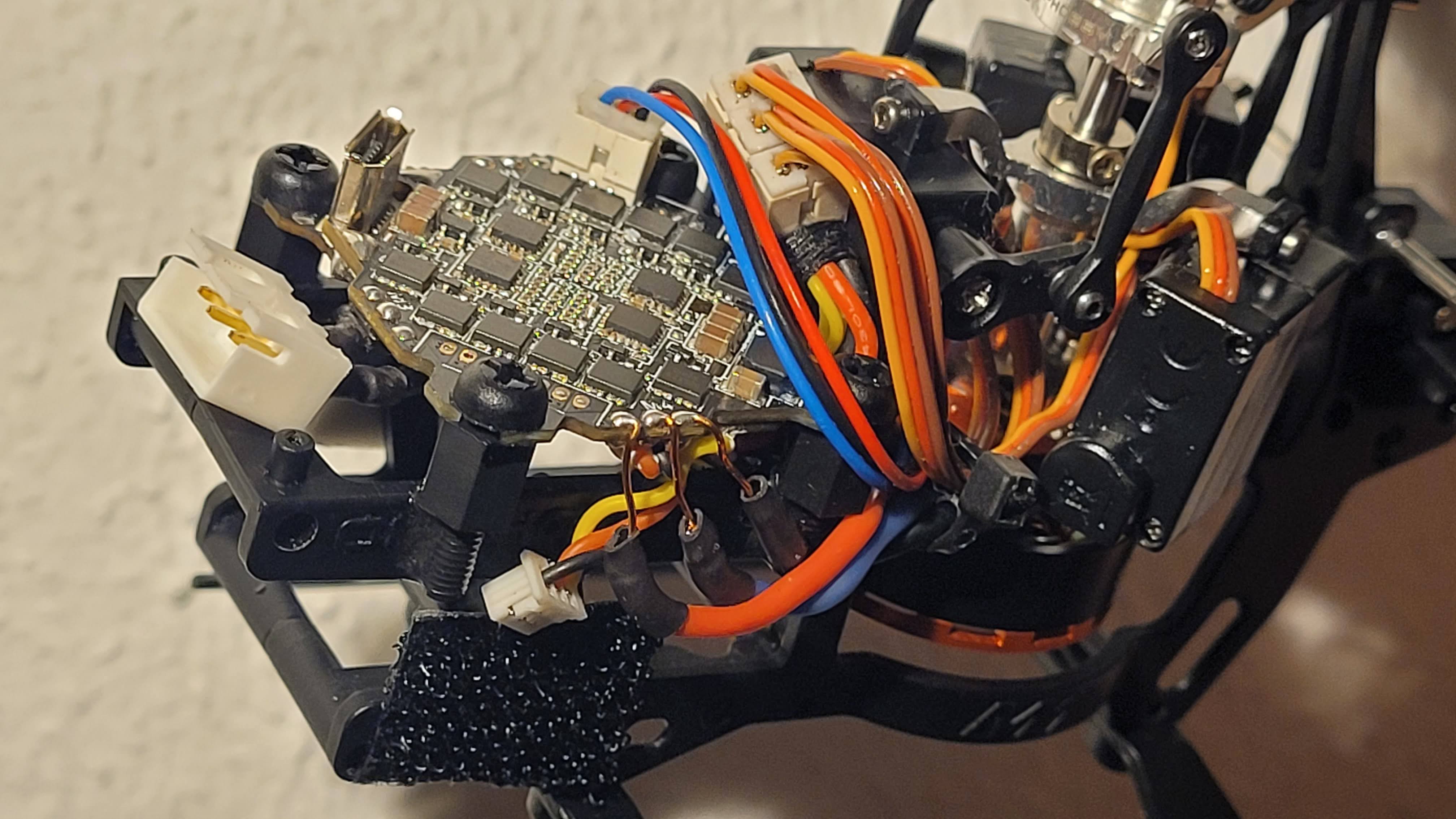
The OpenLager can be placed on the velcro, and also uses a Molex PicoBlade connector.
Resource mapping
Here's the resource mapping used for this build.
resource MOTOR 1 B07   # main motor on M4
resource MOTOR 2 B04   # tail motor on M1
resource MOTOR 3 NONE
resource MOTOR 4 NONE
resource SERVO 1 A00   # RSSI
resource SERVO 2 B03   # S5
resource SERVO 3 A08   # LED strip
resource LED_STRIP 1 NONE
And here's an overview of the pads on the DarwinFPV 15A:
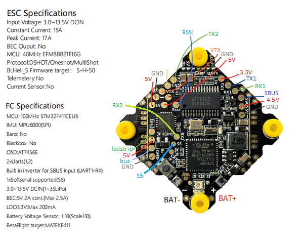
ELRS is on RX1/TX1/4.5V (so it also powers up when connecting USB), OpenLager is on TX2.
Here's the complete diff all.
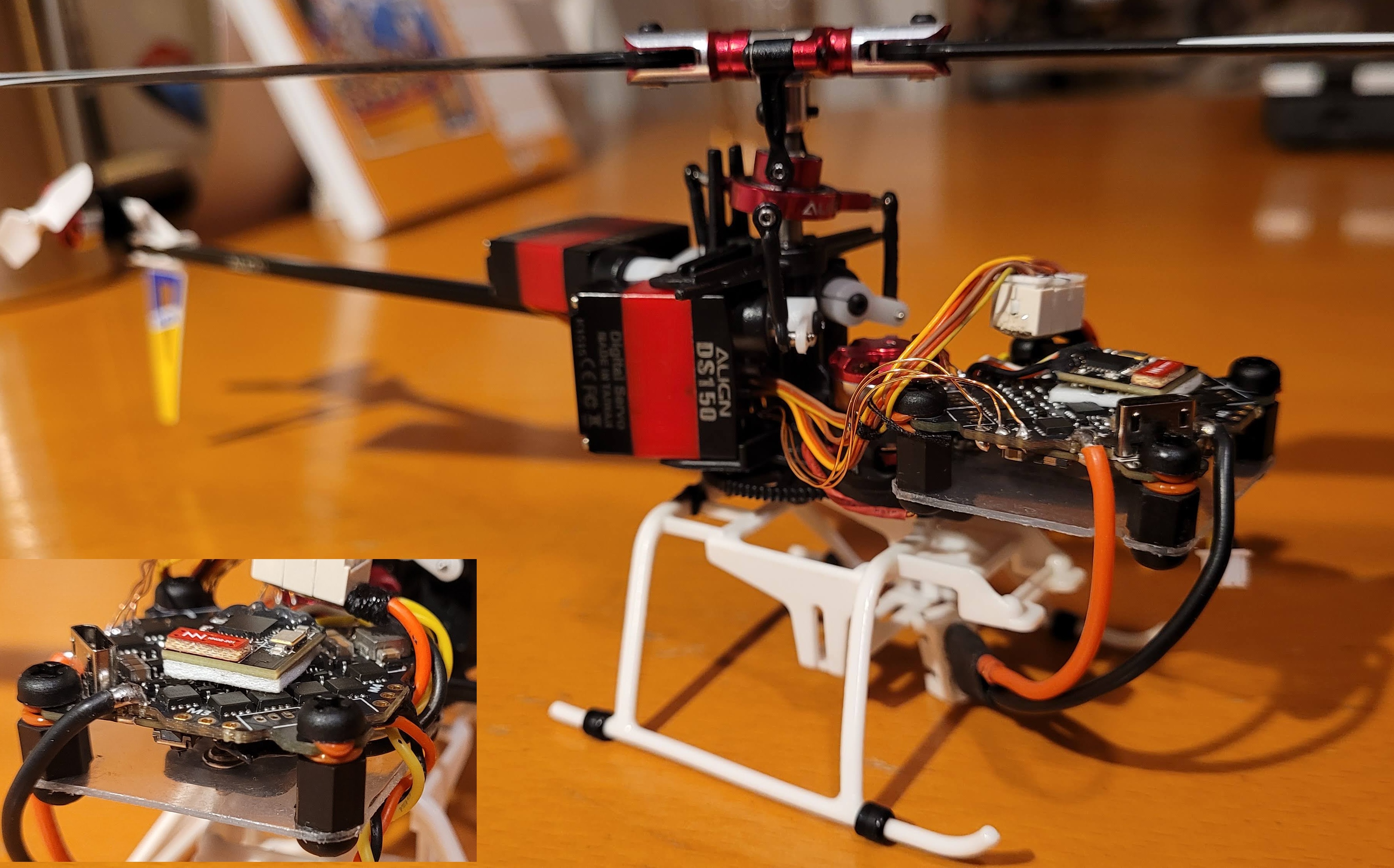
Mounting a flight controller with an MPU-6500 gyro
Some DarwinFPV 15A boards are equipped with an MPU-6500 gyro, which is particularly sensitive to vibrations. Hard mounting the PCB will likely overwhelm the gyro, resulting in oscillations and twitches visible as a noisy, unstable gyro trace. This can be resolved by using for example rubber O-rings around the mounting screws to soft-mount the PCB.
You can check the gyro type on your flight controller using the CLI. Run:
status
The output will look something like this:
MCU F411 Clock=108MHz (PLLP-HSE), Vref=3.29V, Core temp=24degC
Stack size: 2048, Stack address: 0x2001fff0
Configuration: CONFIGURED, size: 5147, max available: 16384
Devices detected: SPI:1, I2C:0
Gyros detected: gyro 1 locked dma
GYRO=MPU6500, ACC=MPU6500
...
The GYRO= field shows the gyro type. In this example, the board has an MPU-6500.