Governor Electric Setup
ELECTRIC is the full Rotorflight governor, tuned for electric motors. It measures the headspeed and actively holds it against collective, cyclic, yaw and a falling battery voltage.
This page walks through the settings that every electric setup needs, and then shows four worked examples covering the common ways of flying a helicopter.
Before you start
The governor cannot work without a reliable headspeed signal and a sane throttle range, so get these right first:
- RPM signal. Set up ESC telemetry or an RPM sensor, and enter the gear ratios and motor pole count in the Motors tab. Check the headspeed reads correctly in the Status tab before going any further.
- Throttle endpoints. In the Motors tab, set the 0% and 100% throttle values so that the motor starts just above 0% and reaches full throttle at 100%. There must be no deadband at either end.
- Throttle channel. Set the active range of the throttle channel in the Receiver tab. The channel must drop below this range for the helicopter to arm.
Remove the main and tail blades before spooling up for the first time with a new governor configuration.
Common settings
On the Governor tab, set Governor Mode to ELECTRIC.
Handover Throttle is the throttle level above which the governor takes over. Below it the throttle input is passed straight to the ESC. The default of 20% suits most electric setups — the only requirement is that the motor will start below this level.
The motor must be able to start below the handover throttle level. If this does not happen using the motor override please check that the ESC does not have the internal Governor enabled.
The headspeed itself is a profile setting. On the Profiles tab, set Full Headspeed to the headspeed you want to fly.
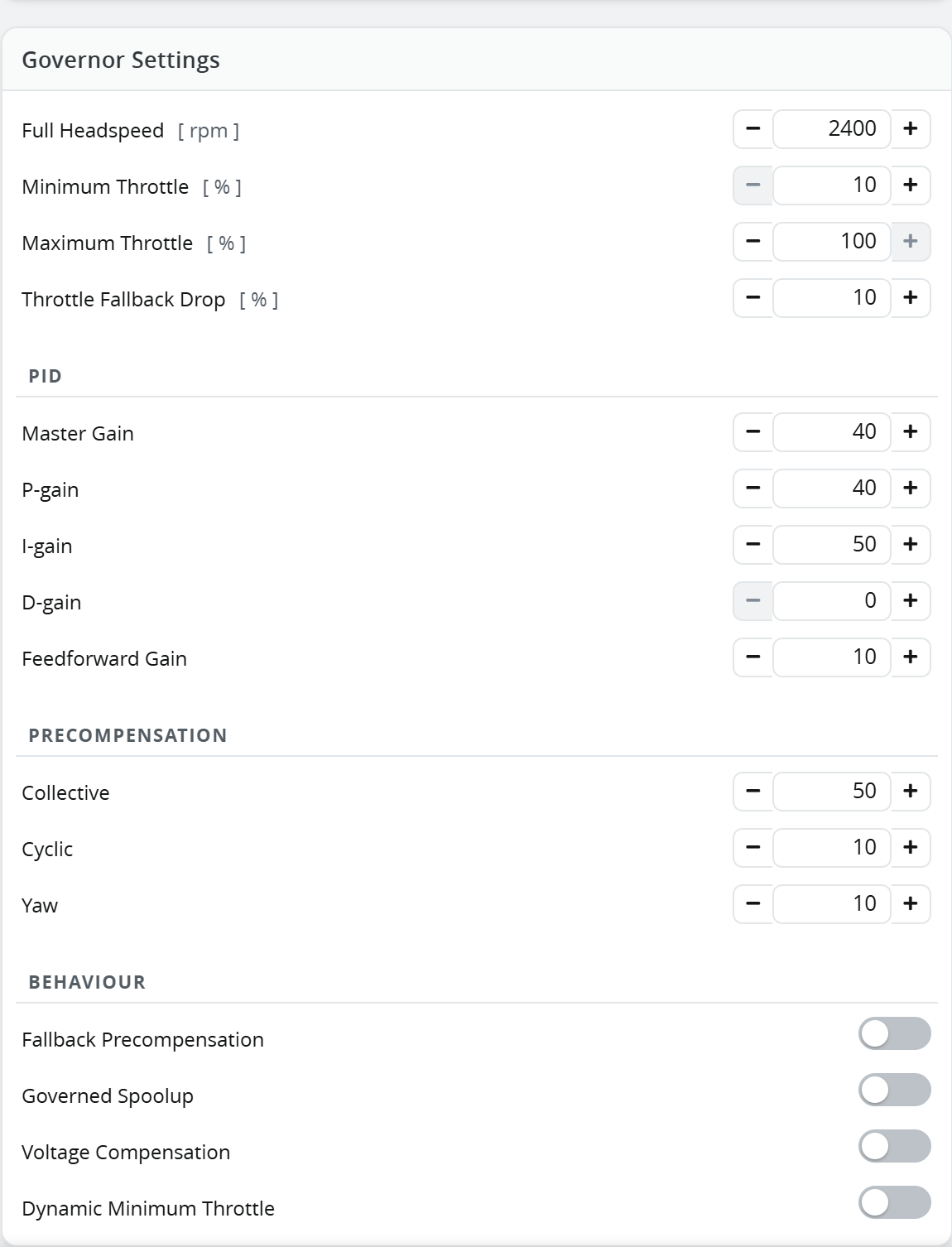
Full Headspeed is per-profile, so different flight profiles can fly different headspeeds.
Example 1 — One headspeed on a throttle cut switch
The simplest setup, and the one most electric pilots use. A single switch in the transmitter cuts the throttle channel to its stop position, or sends it to 100%. The governor flies at Full Headspeed whenever the switch is on.
Set Throttle Type to NORMAL. With this type the throttle input only decides whether the governor runs — it does not scale the headspeed.
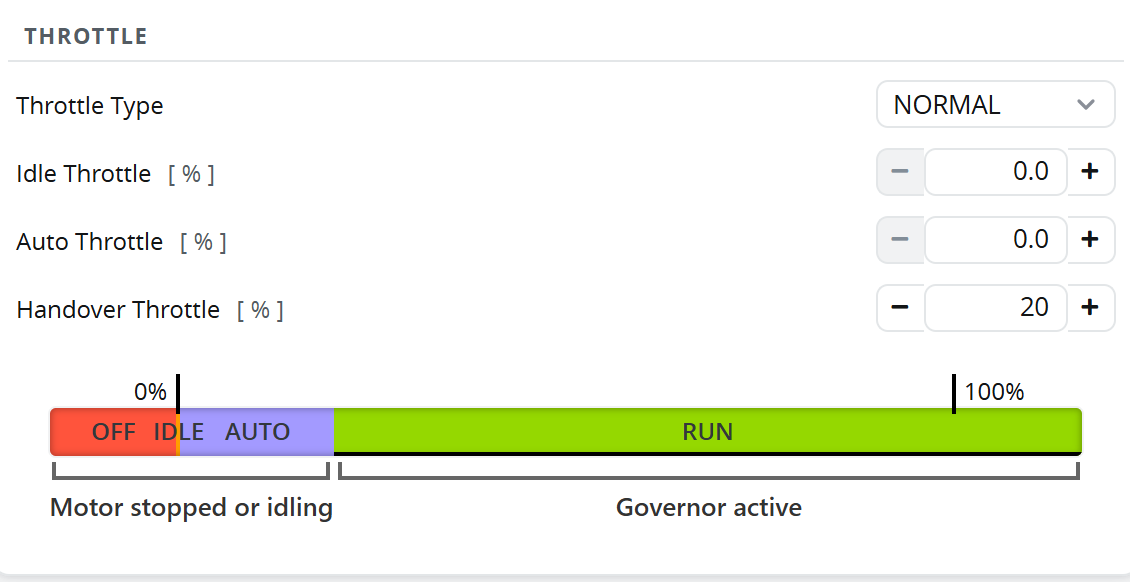
The bar under the settings shows how the throttle channel is divided up.
The bar always draws an AUTO band between Auto Throttle and Handover Throttle, even when autorotation is switched off. It does nothing until you set an Autorotation Timeout — see Adding autorotation bailout.
In the transmitter, assign a switch to the throttle channel with two positions:
| Switch position | Throttle channel |
|---|---|
| Cut | Below the active range (e.g. 988µs) |
| Run | 100% |
Example 2 — Throttle on the stick
A traditional throttle-on-stick setup. The governor settings are identical to Example 1 — Throttle Type stays on NORMAL — and all the work is done by the throttle curve in the transmitter.
Build a normal helicopter throttle curve and make the flat part 100%. Anything above the handover point hands control to the governor, so the shape of the curve below that is yours to choose.
Use a Throttle Cut switch with this setup. Without one there is no quick way to stop the motor.
Example 3 — Two headspeeds on a switch
A three-position switch selects idle, or one of two headspeeds. This is the flight-mode style setup.
Set Throttle Type to SWITCH. Above the handover point the throttle channel no longer controls throttle — it sets the headspeed target as a percentage of Full Headspeed.
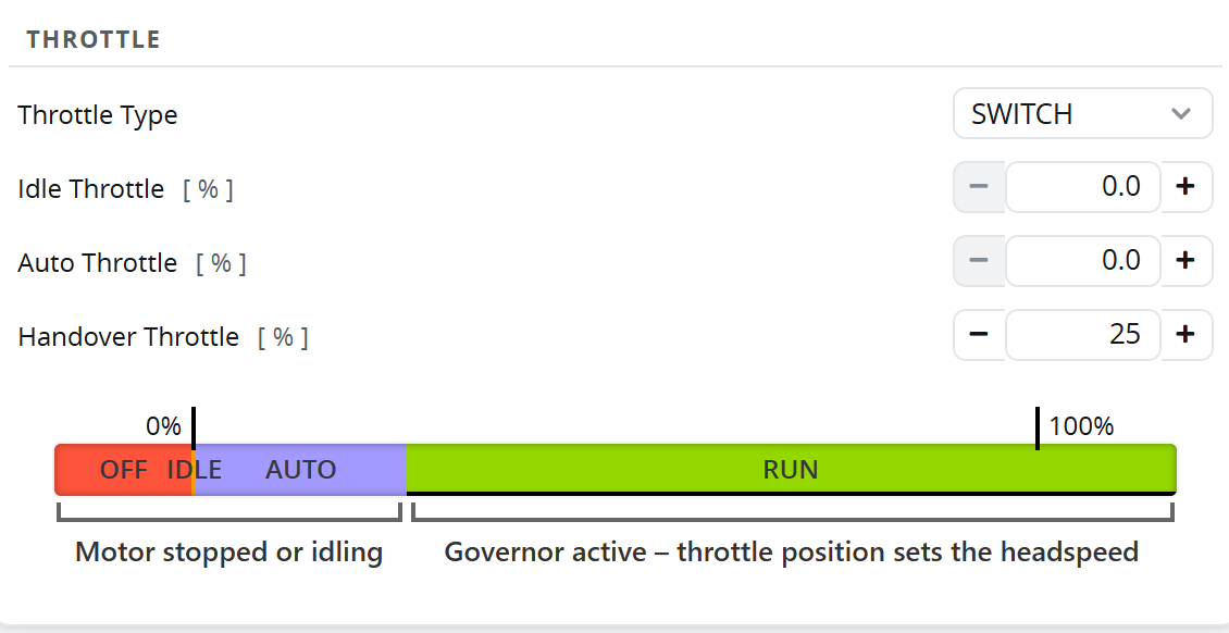
With Full Headspeed set to 2400 rpm and a three-position switch:
| Switch position | Throttle channel | Headspeed |
|---|---|---|
| Idle | Below the active range | Motor stopped |
| Mid | 80% | 1920 rpm |
| High | 100% | 2400 rpm |
The jump between positions must be instantaneous, so this type cannot be used with throttle-on-stick.
Example 4 — ELRS wide mode channel
The wide mode channels in ExpressLRS have too few steps for NORMAL or SWITCH. FUNCTION divides the active range into three equal bands instead, so only coarse positions are needed.
Set Throttle Type to FUNCTION. Idle Throttle and Auto Throttle then set the throttle output used in the IDLE and AUTO bands.
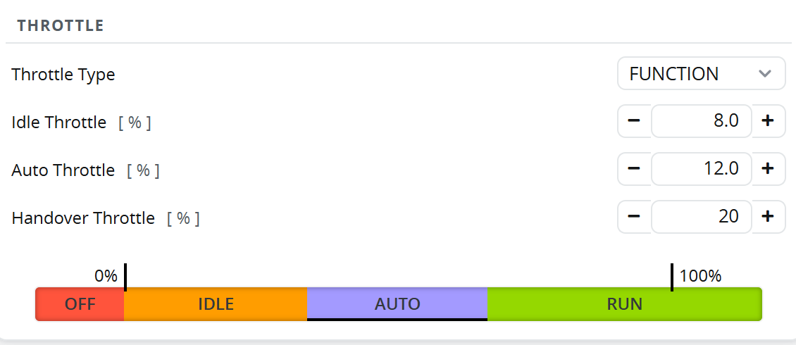
In the transmitter, a Throttle Cut switch sends the channel to the OFF level. When it is not active, a three-position switch selects the band:
| Function | Throttle channel | Result |
|---|---|---|
| OFF | 988µs | Motor stopped |
| IDLE | 1250µs | Motor runs at Idle Throttle |
| AUTO | 1500µs | Motor runs at Auto Throttle |
| RUN | 1750µs | Governor active at Full Headspeed |
NORMAL and SWITCH need a full resolution throttle channel. Use FUNCTION if yours is limited.
Adding autorotation bailout
Any of the examples above can be given a fast bailout. The governor detects an autorotation when the throttle is suddenly dropped into the band between Auto Throttle and Handover Throttle, and spools back up quickly when the throttle is returned.
Set Autorotation Timeout to the longest autorotation you expect — bailout is disabled while this is 0. Then set Auto Throttle to define the autorotation band.
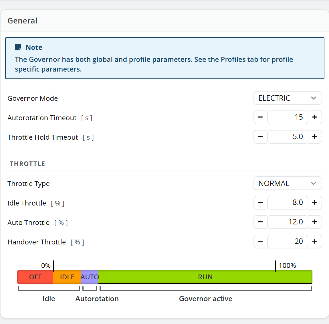
Dropping the throttle below Auto Throttle cancels the autorotation, and the next spoolup is a normal one.
Motor ramp
The Motor Ramp section controls how quickly the throttle may change in each situation. The defaults are a good starting point.
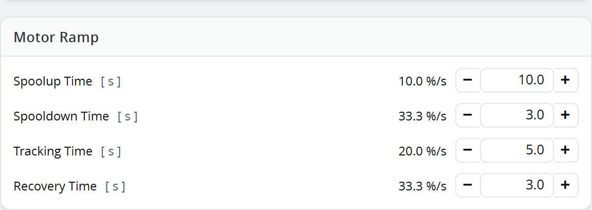
- Spoolup Time — how long a normal spoolup from the ground takes. Raise it for a gentler spoolup.
- Spooldown Time — how quickly the motor is allowed to wind down when the throttle is cut.
- Tracking Time — how quickly the governor moves between headspeeds, as in Example 3.
- Recovery Time — used for an autorotation bailout or after an accidental throttle cut. This is much faster than spoolup, because the helicopter is probably in the air.