Governor
The purpose of the governor is to keep the headspeed constant, regardless of the flight conditions, amount of collective applied, the battery voltage level, and so on.
It is also ensuring safe operation by limiting the spool up and down speeds, and dealing with failure situations.
Basic Operation The Rotorflight RF Governor offers a variety of features, providing flexibility for both traditional throttle-curve setups and modern switch-based (flight-mode) setups. It fully supports electric helicopters as well as nitro/IC (glow) engines.
To enable the governor and access its settings, navigate to the Governor tab in Rotorflight Configurator.
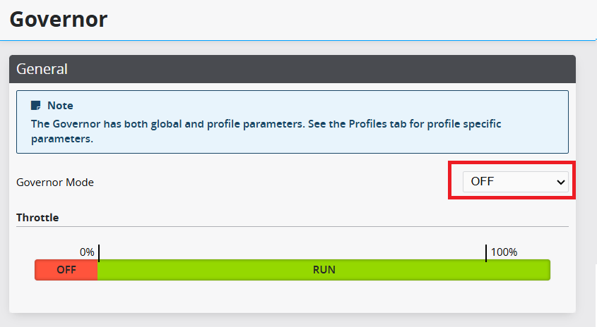
Governor Modes
The governor mode controls what type of governor is used - if any.

Governor Mode OFF
The governor is completely disabled. The input throttle is used as the output throttle.
Governor Mode LIMIT
The governor is completely disabled. The input throttle is used as the output throttle, with gov_idle_throttle, gov_min_throttle and gov_max_throttle applied.
Governor Mode DIRECT
The input throttle is used directly, but with limits and slow spoolup features. The speed governing function is disabled. This mode is intended for use with ESCs that have their own built-in governor but no slow spoolup, or with traditional throttle curves in the transmitter.
This mode does not require an RPM signal.
Governor Mode ELECTRIC
Full Rotorflight governor functionality is enabled, optimised for electric motors. The governor actively maintains the requested headspeed throughout the flight.
Requires an RPM signal from the ESC or a separate RPM sensor.
Governor Mode NITRO
Full Rotorflight governor functionality is enabled, optimised for nitro/IC engines.
Requires a magnetic RPM sensor mounted on the engine or main gear.
Throttle Channel
The throttle channel is the main control for the motor and the governor.
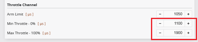
The throttle channel has a defined active range, in which the motor is running. Below this active range, the motor remains stopped. The microsecond values for the active range are configured in the Receiver settings and represented as 0%-100% in the governor.
Example with 1100µs-1900µs active range in ELRS:

Note! In order to arm, the throttle channel must be within the stop range.
The throttle channel settings are configured in the Receiver tab.
Handover Throttle
The handover throttle is a point in the active range, above which the governor is allowed to operate. Throttle values below this point are considered idle.
Example with a 25% handover point:

In Nitro/IC, the clutch must engage below the handover point, i.e. in the idle region.
Throttle Channel Types
Rotorflight provides three throttle channel types, allowing the user to freely choose the one that best matches their preference and transmitter setup.
Throttle Type NORMAL
The throttle channel is controlling the motor throttle directly and continuously. The user can use either throttle-on-stick or throttle-on-switch. The governor will engage once the targeted headspeed is reached, and will maintain it until the throttle is dropped below the handover level.
Slow spoolup can be controlled with the spoolup parameters.
NOTE! NORMAL requires the throttle channel to have full resolution. The wide mode channels in ExpressLRS are not suitable for this purpose.
Throttle Type SWITCH
In the idle region, the throttle channel is directly controlling the throttle. In the active region, the throttle channel governs the headspeed instead.
The transition between idle and run throttle levels shall be instantaneous. A transmitter switch is typically assigned to toggle between these positions. In the active region, multiple discrete throttle positions may be used to select different target headspeeds.
Example with 10% idle; 80% and 90% headspeeds:

NOTE! This throttle type is not compatible with throttle-on-stick.
NOTE! SWITCH requires the throttle channel to have full resolution. The wide mode channels in ExpressLRS are not suitable for this purpose.
Throttle Type FUNCTION
The desired governor function is selected using a switch on the Tx. The throttle level determines one of the following functions: OFF, IDLE, AUTO, RUN.
This throttle type is particularly useful when using limited-resolution channels, like the wide mode channels in ExpressLRS.

Example setup for ELRS
A Throttle Cut switch sets the throttle channel to the OFF level. When TC is not active, another 3-position switch selects between IDLE/AUTO/RUN.

The output throttle for the IDLE and AUTO functions is set with the gov_idle_throttle and gov_auto_throttle parameters.
Output Throttle Settings
The output throttle (servo/ESC) parameters: min_throttle, max_throttle, and min_command must be set properly for the correct governor operation.
The min_throttle and max_throttle set the active range of the output throttle, corresponding to the 0%-100% range in the governor. Any throttle change within this range must have an actual effect on the motor. There must not be any deadbands, where any throttle changes have no effect on the motor RPM or power.
On electric, min_throttle is a value where the motor is not running, but would start just above it. And max_throttle is a value where full throttle (WOT) is reached. It is imperative that the motor will start below 5% throttle, and reach WOT at 100%.
The min_command is a throttle level below min_throttle, where the motor is guaranteed to stop and not run under any circumstances. On electric it's also the level that allows the ESC to arm.
NOTE. min_throttle and max_throttle define the throttle range, that is displayed as 0%..100% in the logs and in the telemetry.
NOTE. Do not set min_throttle to the engine’s idle level. min_throttle should be set low enough that the engine will not sustain an idle and will shut down at this position. This is not the point where the carb barrel is fully closed for engine cut; it is the lowest usable throttle position for idle adjustment.
min_throttle and max_throttle are fixed setup parameters and cannot be adjusted at runtime, whereas gov_idle_throttle can be adjusted dynamically.
Idle Throttle
In the idle throttle region, the throttle value is passed to the output, and the user can configure the desired idling throttle level in the transmitter.
Sometimes a single transmitter model is used with multiple helicopters, and it is preferred to store the idling throttle level in the FC instead.
When gov_idle_throttle is set to a non-zero value, it establishes a minimum motor output throttle. This allows the desired idle throttle level to be defined in the flight controller, while the transmitter may still temporarily output a higher idle throttle value.
Example with 8% idle throttle:

Autorotation
The governor can perform a fast bailout from autorotation if it can detect when autorotation is being attempted. Autorotation is detected when, while the governor is active, the throttle is suddenly reduced to a level within a predefined autorotation range.
In order to enable autorotation detection, the autorotation timeout and the autorotation throttle range must be configured.
Autorotation Timeout
The autorotation timeout defines the maximum duration of an autorotation. After this timeout expires, the governor will no longer initiate a bailout.
Autorotation bailout is disabled unless this timeout is explicitly configured.
Autorotation Throttle Range
The autorotation throttle region is defined by the gov_auto_throttle parameter. Autorotation is detected when the input throttle is above gov_auto_throttle and below gov_handover_throttle.
Autorotation is canceled when the input throttle falls below the autorotation region. A bailout from autorotation is triggered when the input throttle rises above the handover throttle.
Example with 12% auto throttle:

Governor States
The governor operates in multiple states. Each state represents a different scenario, with different functionality and different parameters. For example, spoolup, active, etc.
The governor is automatically moving between the states, based on the throttle channel value, the motor behaviour, and the previous state.
The governor state is available as a telemetry sensor, and can be displayed on the transmitter.
State THROTTLE_OFF
The motor is turned off. The value min_command is sent to the ESC/servo.
State THROTTLE_IDLE
The throttle is below handover, and the motor is either stopped or running slow. The input throttle is passed to the output, but change speed is limited by gov_startup_time.
The helicopter is expected to be on the ground.
State THROTTLE_HOLD
The input throttle was switched off while in the ACTIVE state. The motor is spooling down. If the throttle is restored within gov_throttle_hold_timeout, a fast recovery is performed.
This is a safeguard against an accidental Throttle Cut activation.
State SPOOLUP
The input throttle was increased above handover, and the motor is spooling up to the required headspeed. The change speed is limited by gov_spoolup_time.
Once the target headspeed is reached, the governor moves to the ACTIVE state.
State RECOVERY
The governor is recovering from FALLBACK or THROTTLE_HOLD, i.e. going back to ACTIVE. This is done with a much faster spoolup speed than in SPOOLUP, as the helicopter is likely airborne. The throttle change is limited by gov_recovery time.
State ACTIVE
The governor is locked on the target headspeed, and the throttle is controlled by the PID loop. Precomps from collective, cyclic, and yaw are applied.
If the target headspeed is altered, the change speed is limited by gov_tracking_time.
State FALLBACK
RPM signal is unreliable or lost, and the headspeed can't be controlled. Instead, an estimated throttle value is used, with optional precomps, so that the pilot can land the helicopter safely.
The parameter gov_fallback_drop sets the percentage of throttle drop for indicating this condition, in order to notify the pilot.
State AUTOROTATION
Throttle is above autorotation throttle, but below handover, and autorotation is active. Similar to THROTTLE_IDLE, but the helicopter is expected to be airborne. If the throttle is returned, a fast BAILOUT is performed.
After a successful landing, the pilot is expected to disable autorotation by moving to an idle throttle level, and proceed with a normal SPOOLUP.
State BAILOUT
The autorotation attempt was abandoned, and an autorotation bailout is performed. Throttle is ramped up quickly, according to the gov_recovery_time parameter.
State BYPASS
The governor is temporarily disabled, and the throttle is passed to the ESC unaltered. The throttle value is calculated from the collective position, using gov_bypass_throttle.
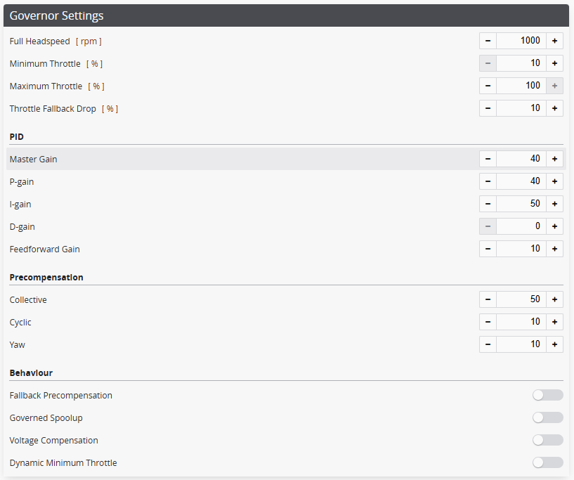
Settings The governor has both global and profile settings. Global settings are always valid. Profile settings are applied only when a profile is active.
Motor Ramp
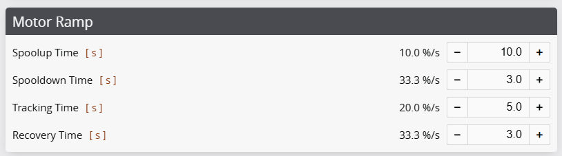
Spoolup Time
The throttle change speed limit for SPOOLUP state. It is the time it takes from idle to full throttle. This is the main parameter for controlling the spoolup aggressiveness.
Spooldown Time
The throttle change speed limit for spooldown, which occurs when the throttle is dropped below handover while in ACTIVE state. It is the time it takes to spool down from full throttle to idle. This is a safety feature to prevent sudden throttle drops in case of an accidental Throttle Cut activation.
Recovery Time
The throttle change speed limit for RECOVERY and BAILOUT states. It is the time it takes to recover from a throttle drop or autorotation attempt. This should be set much faster than spoolup time, as the helicopter is likely airborne in these scenarios.
Tracking Time
The throttle change speed limit for changes in target headspeed while in ACTIVE state. This is the time it takes for the governor to adjust to a new headspeed target. This should be set faster than spoolup time, but not too fast to cause oscillations in the throttle.
Governor Profile settings